Uni-Housing™ Pressurized Enclosures
McGill AirFlow Uni-Housing enclosures are an excellent choice for enclosing many types of HVAC equipment for both pressurized and nonpressurized applications. They are designed for low leakage, provide excellent thermal and acoustical control, and facilitate easy on-site assembly for indoor or outdoor applications. And depending on the application or size of the enclosure, McGill AirFlow can deliver the finished enclosure or the subassemblies to the jobsite.
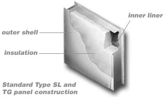
Uni-Housings can be constructed from McGill AirFlow's Type SL or Type TG acoustical panel systems. The Type SL and Type TG panels are identical except for their panel joint designs. The Type SL panel has a self-locking (snap-lock) design that offers quick assembly and is used in applications where disassembly is not a primary concern. The Type TG panel has a simple tongue-and-groove design that is recommended when future disassembly and re-erection of the enclosure may be required. Both panels have a sandwich-type construction consisting of a solid galvanized steel outer shell, acoustical/thermal insulating fill, and a perforated inner liner of galvanized steel. All of the standard wall, door, roof, and floor panels are available with either the snap-lock joint design or tongue-and-groove joint design.
Standard Panel Construction
The Type SL Panel
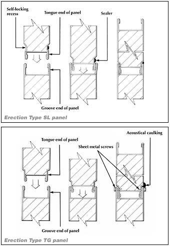
A special built-in connection system allows the Type SL panels to snap-lock together, forming a low-leakage, structurally sound, full-length joint. This mechanical interlocking joint requires no sheet metal screws. The three-step panel locking sequence shown illustrates the snap-lock action of the connection. First, one panel is started into the structural channel of the next panel. As the panels are pushed together, the locking lugs spring out and then snap back into position as the connection process is completed. Sealer, which is placed in the outside panel groove prior to connection, is hydraulically extruded in place as the panels are snap-locked together.
The Type TG Panel
The Type TG panels utilize a tongue-and-groove joint design where the tongue end of one panel slips into the groove end of the adjoining panel. Fasteners (screws) are required for securing the panel joint. For installations where disassembly and re-erection may be required, it is recommended that a removable joint sealer be used instead of the standard McGill AirSeal United Duct Sealer™ sealant.
Material
Both SL and TG panels are available in a standard 4-inch thickness. A 2-inch thickness is optional, with other thicknesses available by special order. Standard panel widths are 24 inches and 36 inches, with standard lengths up to 12 feet. Other widths and longer lengths are also available through special order. For most enclosures, at least one special-width panel will be required as a fill-in panel to match the specified dimensions of each wall, floor, or roof assembly. Also, in most cases, maximum panel lengths will be determined by the working design pressures.
The standard material for both the outer shell and inner liner is galvanized steel. It can be specified as either solid or perforated and has a minimum G-60 zinc coating. The perforated steel has 23 percent open area. Many different material and gauge combinations of outer shell and inner liner can be selected, with the inner liner being either solid or perforated.
The standard acoustical/thermal fill material used in Type SL and Type TG panels is 1.55 pcf fiberglass, giving the standard 4-inch-thick panel an R17 value. The fill will not settle or promote the growth of bacteria, mold, vermin, or insects. A moisture barrier can also be specified. This consists of one layer of polyethylene plastic separating the insulation from the inner perforated metal liner.
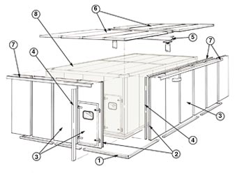
Assembly and Installation Sequence of a Uni-Housing™ Enclosure
Installation Sequence:
A special built-in connection system allows the Type SL panels to snap-lock together, forming a low-leakage, structurally sound, full-length joint. This mechanical interlocking joint requires no sheet metal screws. The three-step panel locking sequence shown illustrates the snap-lock action of the connection. First, one panel is started into the structural channel of the next panel. As the panels are pushed together, the locking lugs spring out and then snap back into position as the connection process is completed. Sealer, which is placed in the outside panel groove prior to connection, is hydraulically extruded in place as the panels are snap-locked together.
- Locate base channel.
- Set corner panels.
- Install wall, partition, and door panels.
- Add wall trim - outside and inside.
- Add structural steel (as required).
- Add roof panels.
- Add roof trim - outside and inside.
- Complete Uni-Housing enclosure.
Uni-Housing™ Applications
- Built-up air handling and fan system enclosures
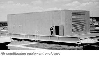
- Air conditioning equipment enclosures
- Outside air intake plenums
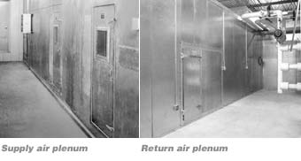
- Supply/return air handling and fan system plenums
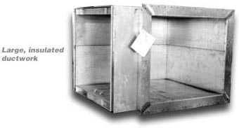
- Large rectangular duct systems fabricated from Uni-Housing panels
Suggested Specifications for Uni-Housing™ HVAC Acoustical Panel Systems
General
Double-wall (insulated) acoustical enclosures shall be provided as specified on drawings. All panels and components shall be prefabricated and supplied by a nationally-recognized manufacturer with published standards of construction, assembly, and technical performance. The manufacturer shall have produced a standardized, prefabricated panel system for at least 10 years. Construction and performance of the installed system and components shall conform to all specifications listed in this document. The system and components shall not be susceptible to damage from extended exposure to airflow, pressure differentials, vibration, air temperature, or humidity.
Joint Construction
Enclosure panels shall have either a snap-lock joint construction or a tongue-and-groove joint construction. Panels with snap-lock joint construction shall be such that adjacent panels are held together rigidly with an integral, continuous, self-locking joint on both inside and outside panel surfaces. Panels with tongue-and-groove joint construction will be held together with fasteners such as screws. Neither panel types should require H-connectors, tape, or any other type of additional connectors.
Panel Construction
- All panels shall be 2 or 4 inches thick, as noted on the drawings, with a solid galvanized steel exterior shell, and a solid or perforated interior galvanized steel shell as noted on the drawings.
- The outer and inner shells shall be tack or spot welded to perimeter and internal longitudinal steel channels and box-end internal closures, in such a manner and spacing that the panel assembly will not fail at the maximum operating loads specified in Structural Performance.
- The outer shell shall be constructed of galvanized steel with a minimum 20-gauge thickness.
- The inner shell shall be constructed of galvanized steel (solid or perforated) with a minimum 22-gauge thickness.
- Perforated material shall have a 23 percent open area.
- All perimeter and internal longitudinal steel channel members shall be constructed of ASTM Type A-653 commercial-quality galvanized steel with a minimum 18-gauge thickness.
- All steel panel surfaces, internal channels, and trim items shall be fabricated from zinc-coated steel with a dipped galvanized coating (minimum G-60 coating class as determined by ASTM A-924) and shall meet all requirements of ASTM A-653 for commercial-quality galvanized carbon steel.
- Each enclosure panel shall be completely filled with acoustical/thermal insulating material that is noncombustible, inert, mildew-resistant, and vermin-proof. Insulation shall not settle within the enclosure panel. No insulating materials shall be used that have a flame spread greater than 25 or a smoke developed greater than 50.
- Where specified on the drawings, septum panels shall consist of a solid galvanized steel sheet (minimum 20-gauge thickness) centrally sandwiched between layers of insulating material and perforated galvanized steel outer sheets (minimum 22-gauge thickness). The solid steel inner sheet shall be framed and sealed so that air does not leak through the enclosure when a pressure differential exists.
Components and Installation
- All base channels shall be installed on a level concrete curb, the dimensions of which shall be determined from plan-view shop drawings of the system provided by the system manufacturer. Spacing of base channel attachments shall be as outlined in the manufacturer's standard details of assembly.
- All assembly trim items shall be constructed of hot-dipped galvanized steel (minimum 18-gauge thickness) and furnished in standard lengths to be field cut to the required dimensions. Spacing of sheet metal screws, application of duct sealant, and positioning of trim shall be in accordance with the manufacturer's published erection and installation details.
- All mechanical joints and external trim items shall be sealed with a UL-Classified duct sealant in accordance with Section 4 or 5. In order to show that joints have been sealed properly, enough sealant shall be used so that excess sealant is extruded from all completed external joints.
- For enclosures to be installed indoors, joints and trim shall be sealed with United Duct Sealer™ (Water Based), formulated to withstand temperatures from -25°F to +200°F. Sealant shall be formulated such that surface preparation or solvent cleaning is not necessary. Sealant shall have a UL Classification marking with flame spread of 5 and smoke developed of 0 when applied to 18-gauge galvanized steel or inorganic reinforced cement board, both at a coverage of 31 square feet per gallon. Sealant shall exceed 500 hours without becoming brittle under ASTM-D572 test conditions (oxygen bomb).
- For enclosures to be installed indoors and outdoors, joints and trim shall be sealed with Uni-Weather™ solvent-based duct sealant that is a neoprene-phenolic mastic formulated to withstand temperatures from -20°F to +300°F. Sealant shall be formulated such that surface preparation or solvent cleaning is not necessary. Sealant shall have a UL Classification marking with a flame spread of 5 and smoke developed of 0 when applied to 18-gauge galvanized steel and a flame spread of 5 and smoke developed of 5 when applied to inorganic reinforced cement board, both at a coverage of 53 square feet per gallon. Sealant shall exceed 1,000 hours under ASTM-D572 test conditions (oxygen bomb) without becoming brittle and 500 hours in QUV accelerated-exterior-aging apparatus without degradation (under ASTM-C732 test conditions).
- Acoustical personnel access doors shall be provided where specified on drawings and shall be 24 inches wide by 60 inches high unless otherwise indicated. All doors shall be the same nominal thickness as the adjacent panels. All access door panels and doors shall be constructed with an 18-gauge solid inner and outer shell. Each door shall have a minimum of two ball-bearing hinges and two wedge-lever door latches. All levers shall be installed to open against the air pressure differential. Doors shall seat against neoprene gasket materials, installed around the entire perimeter of the door frame in such a manner that door operation will provide direct compression with no sliding action between the door and gasket.
- Where shown on drawings, acoustical doors shall be furnished with windows, which are composed of double-glazed layers of wire-reinforced safety glass, separated by an air space, and sealed against acoustical and air leakage by interior and exterior rubber seals. Windows shall be 12 inches wide by 12 inches high unless otherwise indicated.
- Openings for pipe and conduits shall be field cut to ensure proper positioning. All framing members, collars, and bellmouth fittings shall be insulated, welded, and sealed according to the manufacturer's published installation details.
Structural Performance
- The entire enclosure shall be designed by the manufacturer to be self supporting. Where roof spans and wall loadings require additional structural strength, it shall be provided by heavier panel skins, additional internal longitudinal reinforcing members, or additional structural members and necessary supporting pipe columns. The installer shall furnish and install all structural members and pipe columns according to the drawings and published installation details provided by the manufacturer.
- The finished enclosure shall be able to withstand a positive internal static pressure of ( ) inches wg and a negative internal static pressure of ( ) inches wg. Installations subjected to the effects of weather shall be able to withstand a wind loading of ( ) pounds per square foot.
- Under the conditions specified in the previous section, the assembled structure shall not exhibit any panel joint deflections in excess of L/200, where L is the unsupported span length of any panel section within the completed enclosure.
Acoustical Performance
- The manufacturer shall provide certified testing data obtained from an acoustical laboratory, listing sound absorption and transmission loss characteristics of the enclosure. When requested by the engineer, the manufacturer shall arrange to have a copy of all pertinent acoustical laboratory reports forwarded directly from the laboratory to the engineer.
-
When tested according to ANSI/ASTM Standard C423 or a subsequent version of the standard, the enclosure shall have minimum sound absorption coefficients, as shown in the table below, in the 1/3 octave band center frequencies. The coefficients used shall be those reported by the acoustical laboratory.
Sound Absorption Coefficients Octave Band (Hz) 125 250 500 1,000 2,000 4,000 NRC 4-inch panel construction 0.63 1.09 1.17 1.08 1.03 0.97 1.09 2-inch panel construction 0.22 0.64 1.06 1.06 0.98 0.87 0.94 Sound Absorption Coefficients Octave Band (Hz) 4-inch panel construction 2-inch panel construction 125 0.63 0.22 250 1.09 0.64 500 1.17 1.06 1K 1.08 1.06 2K 1.03 0.98 4K 0.97 0.87 NRC 1.09 0.94 -
When tested according to ASTM E90 or a subsequent version of this standard, the enclosure panel shall have minimum airborne sound transmission losses in the combined full octave band center frequencies as listed below:
Sound Transmission Losses Octave Band (Hz) 125 250 500 1,000 2,000 4,000 1K 2K 4K STC for 4-inch panels 16 24 35 45 53 58 37 for 2-inch panels 18 21 29 38 49 55 33 Sound Transmission Losses Octave Band (Hz) for 4-inch panels for 2-inch panels 125 16 18 250 24 21 500 35 29 1K 45 38 2K 53 49 4K 58 55 STC 37 33
Thermal Performance
- Insulating materials used in all prefabricated enclosure panels shall have the following maximum thermal conductances at a mean temperature of 75°F: 0.06 BTU per hour per square foot per °F (for 4-inch panels) and 0.12 BTU per hour per square foot per °F (for 2-inch panels).